Capacitors - NEET Physics Questions
Question 1: difficult

A parallel plate condenser is filled with two dielectrics as shown in figure. Area of each plate is A metre² and the separation is d metre. The dielectric constants are K1 and K2 respectively. Its capacitance in farad will be :


1. \[\frac{\varepsilon_{0A}}{d}\left( K_{1} +K_{2}\right)\]
2. \[\frac{\varepsilon_{0A}}{d}\frac{\left( K_{1} +K_{2}\right)}{2}\]
3. \[\frac{\varepsilon_{0A}}{d}2\left( K_{1} +K_{2}\right)\]
4. \[\frac{\varepsilon_{0A}}{d}\frac{\left( K_{1} -K_{2}\right)}{2}\]
View Answer

Both the parts can be taken as separate capacitors connected in parallel.

So, C=C1+ C2=\(\frac{\varepsilon_{0A}}{d}\frac{\left( K_{1} +K_{2}\right)}{2}\)

Question 2: difficult

When the key K is pressed at t = 0, which of the following statements about the current I in the resistor AB of the given circuit is true ?

1. I = 2 mA at all t
2. I oscillates between 1 mA and 2 mA
3. I = 1 ma at all t
4. at t = 0, I = 2mA and with time it goes to 1 mA
View Answer

At t =0 capacitor behaves as closed circuit to the 1000 ohm resistor connected in parallel with capacitor will get short circuited.

current  through the other resistor = 2/1000 = 2mA

At t = infinite capacitor behaves as open circuit so equivalent resistance becomes R=1000+1000 = 2000 Ohm

current  through the  resistor = 2/2000 = 1 mA

Question 3: difficult

A capacitor of capacitance C is initially charged to a potential difference of V volt. Now it is connected to a battery of 2V Volt with opposite polarity. The ratio of heat generated to the final energy stored in the capacitor will be

1. 1.75
2. 2.25
3. 2.5
4. 1/2
View Answer
Question 4: difficult

The plates S and T of an uncharged parallel plate capacitor are connected across a battery. The battery is then disconnected and the charged plates are now connected in a system as shown in the figure. The system shown is in equilibrium. All the strings are insulating and massless. The magnitude of charge on one of the capacitor plates is: [Area of plates = A]

1. \[\sqrt{2mgA \epsilon_{0}}\]
2. \[\sqrt\frac{{4mgA \epsilon_{0}}}{k}\]
3. \[\sqrt{mgA \epsilon_{0}}\]
4. \[\sqrt\frac{{2mgA \epsilon_{0}}}{k}\]
View Answer

To solve this, let us analyze the situation and derive the required expression for the charge:


1. Setup of the System

  • The parallel plate capacitor is initially charged, and the battery is disconnected.
  • One plate of the capacitor is connected to a spring, and the other is attached to a mass
    mm
     

    .

  • The capacitor plates attract each other due to the opposite charges, generating an electrostatic force.

2. Equilibrium Condition

In equilibrium, the upward force due to the spring's tension balances the downward gravitational force acting on the mass

mm

:


T=mgT = mg


This tension

TT

is equal to the electrostatic force

FelecF_{\text{elec}}

between the plates of the capacitor:


Felec=Q22ϵ0AF_{\text{elec}} = \frac{Q^2}{2 \epsilon_0 A}


3. Force Balance

At equilibrium:


Felec=mgF_{\text{elec}} = mg


Substitute

Felec=Q22ϵ0AF_{\text{elec}} = \frac{Q^2}{2 \epsilon_0 A}

:


Q22ϵ0A=mg\frac{Q^2}{2 \epsilon_0 A} = mg


4. Solve for QQ


Rearranging for

QQ

:


Q2=2mgϵ0AQ^2 = 2 mg \epsilon_0 A


Taking the square root:


Q=2mgϵ0AQ = \sqrt{2 mg \epsilon_0 A}


Final Answer:

The magnitude of the charge on one of the capacitor plates is:


Q=2mgAϵ0Q = \sqrt{2mgA\epsilon_0}


Question 5: difficult

Consider the arrangement of three plates X, Y and Z each of area A and separation d. The energy stored in the system when the plates are fully charged is:

1. \[\frac{\varepsilon_{0}AV^{2}}{2d}\]
2. \[\frac{\varepsilon_{0}AV^{2}}{d}\]
3. \[\frac{2\varepsilon_{0}AV^{2}}{d}\]
4. \[\frac{3\varepsilon_{0}AV^{2}}{2d}\]
View Answer

To solve for the energy stored in the system of three plates (X, Y, Z), let's break the system into simpler components:


1. System Description

  • The arrangement forms two capacitors:
    • Capacitor 1: Between plates X and Y.
    • Capacitor 2: Between plates Y and Z.
  • Each capacitor has the same plate area
    AA
     

    and plate separation dd 

    .

The capacitance of a parallel plate capacitor is given by:


C=ε0AdC = \frac{\varepsilon_0 A}{d}


Thus, the capacitance of each capacitor is:


C1=C2=ε0AdC_1 = C_2 = \frac{\varepsilon_0 A}{d}


2. Effective Capacitance

The two capacitors are in parallel because plate Y is connected to the battery on one side and plate X and Z are on the opposite side. For capacitors in parallel, the effective capacitance is:


Ceq=C1+C2C_{\text{eq}} = C_1 + C_2


Ceq=ε0Ad+ε0Ad=2ε0AdC_{\text{eq}} = \frac{\varepsilon_0 A}{d} + \frac{\varepsilon_0 A}{d} = \frac{2 \varepsilon_0 A}{d}


3. Energy Stored in the System

The energy stored in a capacitor is:


U=12CeqV2U = \frac{1}{2} C_{\text{eq}} V^2


Substitute

Ceq=2ε0AdC_{\text{eq}} = \frac{2 \varepsilon_0 A}{d}

:


U=122ε0AdV2U = \frac{1}{2} \cdot \frac{2 \varepsilon_0 A}{d} \cdot V^2


U=ε0AV2dU = \frac{\varepsilon_0 A V^2}{d}


Final Answer:

The energy stored in the system is:


U=ε0AV2dU = \frac{\varepsilon_0 A V^2}{d}


Question 6: difficult

Three capacitors 2 μF, 3 μF and 5 μF can withstand voltages to 3V, 2V and 1V respectively. Their series combination can withstand a maximum voltage equal to

1. 5 Volts
2. (31/6) Volts
3. (26/5) Volts
4. None
View Answer

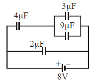
Let's verify and calculate the correct answer step-by-step:

Given Data:

  • Capacitances:
    C1=2μF,C2=3μF,C3=5μFC_1 = 2 \, \mu\text{F}, C_2 = 3 \, \mu\text{F}, C_3 = 5 \, \mu\text{F}
     
  • Maximum voltages:
    V1=3V,V2=2V,V3=1VV_1 = 3 \, \text{V}, V_2 = 2 \, \text{V}, V_3 = 1 \, \text{V}
     

Step 1: Maximum charge each capacitor can store:


Q1=C1V1=23=6μCQ_1 = C_1 \cdot V_1 = 2 \cdot 3 = 6 \, \mu\text{C}


Q2=C2V2=32=6μCQ_2 = C_2 \cdot V_2 = 3 \cdot 2 = 6 \, \mu\text{C}


Q3=C3V3=51=5μCQ_3 = C_3 \cdot V_3 = 5 \cdot 1 = 5 \, \mu\text{C}


The capacitor with the minimum charge capacity limits the system. Here,

Qmax=5μCQ_{\text{max}} = 5 \, \mu\text{C}

, dictated by

C3C_3

.


Step 2: Voltage distribution across each capacitor:

In series, charge

QQ

is the same on all capacitors, and the voltage across each capacitor is:


V1=QC1,V2=QC2,V3=QC3V_1 = \frac{Q}{C_1}, \quad V_2 = \frac{Q}{C_2}, \quad V_3 = \frac{Q}{C_3}


Total voltage across the series combination:


Vtotal=V1+V2+V3V_{\text{total}} = V_1 + V_2 + V_3


Substitute

Q=5μCQ = 5 \, \mu\text{C}

:


V1=52=2.5V,V2=531.67V,V3=55=1VV_1 = \frac{5}{2} = 2.5 \, \text{V}, \quad V_2 = \frac{5}{3} \approx 1.67 \, \text{V}, \quad V_3 = \frac{5}{5} = 1 \, \text{V}


Step 3: Total voltage:


Vtotal=V1+V2+V3=2.5+1.67+1=156+106+66=316V.V_{\text{total}} = V_1 + V_2 + V_3 = 2.5 + 1.67 + 1 = \frac{15}{6} + \frac{10}{6} + \frac{6}{6} = \frac{31}{6} \, \text{V}.


Final Answer:

The maximum voltage the series combination can withstand is:


316V5.17V.\boxed{\frac{31}{6} \, \text{V}} \approx 5.17 \, \text{V}.


Question 7: difficult

A combination of capacitors is set up as shown in the figure. The magnitude of the electric field, due to a point charge Q (having a charge equal to the sum of the charges on the 4μF and 9μF capacitors), at a point distant 30 m from it, would equal :

1. 480 N/C
2. 240 N/C
3. 360 N/C
4. 420 N/C
View Answer
Question 8: difficult

Two spherical conductors A1 and A2 of radii r1 and r2 are placed concentrically in air. The two are connected by a copper A wire as shown in figure. Then the equivalent capacitance of the system is :

1. \[\frac{4\pi\varepsilon_{0}Kr_{1}r_{2}}{r_{2}-r_{1}}\]
2. \[4\pi\varepsilon_{0}(r_{2}+r_{1})\]
3. \[4\pi\varepsilon_{0}r_{2}\]
4. \[4\pi\varepsilon_{0}r_{1}\]
View Answer

The problem involves two spherical conductors

A1A_1

and

A2A_2

connected by a copper wire. Let’s analyze and compute the equivalent capacitance of the system.

Given:


  • A1A_1
     

    and A2A_2 

    are concentric spherical conductors.

  • Radii of the spheres:
    r1r_1
     

    (inner) and r2r_2 

    (outer).

  • The medium is air, so the permittivity is
    ε0\varepsilon_0
     

    .

Key Concepts:

  1. Potential Difference Between the Spheres: The two conductors are connected by a wire, meaning they are at the same potential. As a result, the electric field exists only between the two spheres.
  2. Capacitance of a Single Isolated Sphere: If only
    A2A_2
     

    existed as a spherical conductor, its capacitance would be: 

    Csingle=4πε0r2.C_{\text{single}} = 4 \pi \varepsilon_0 r_2. 

  3. Why the System is Equivalent to an Isolated Sphere: Since
    A1A_1
     

    is connected to A2A_2 

    via a conducting wire, any charge added to A1A_1 

    immediately flows to A2A_2 

    , making the system behave as if there is only one conductor of radius r2r_2 

    .

Equivalent Capacitance:

Thus, the capacitance of the system is:


Cequivalent=4πε0r2.C_{\text{equivalent}} = 4 \pi \varepsilon_0 r_2.


Final Answer:

The equivalent capacitance of the system is:


4πε0r2.\boxed{4 \pi \varepsilon_0 r_2}.


Question 9: difficult

The equivalent capacitance between A and B is :

1. 5C/7
2. 7C/5
3. 7C/12
4. 12C/7
View Answer

To find the equivalent capacitance for this cubical capacitor network, where each edge of the cube has a capacitance

CC

, here’s the shortest solution:

Step-by-Step:

  1. Symmetry analysis:
    • By symmetry, all corners of the cube can be grouped into equivalent potential nodes.
    • The cube's symmetry allows reduction to a simpler circuit.
  2. Key nodes:
    • Node
      AA
       

      is connected to one corner of the cube.

    • Node
      BB
       

      is connected to the diagonally opposite corner.

  3. Effective connections:
    • Due to symmetry, three capacitors are effectively in parallel between
      AA
       

      and an intermediate point.

    • Similarly, three capacitors are effectively in parallel between
      BB
       

      and the same intermediate point.

    • Two capacitors remain directly between
      AA
       

      and BB 

      .

  4. Simplification:
    • The three parallel capacitors at each node result in:
      Cparallel=3CC_{\text{parallel}} = 3C
       
    • The equivalent circuit becomes two
      3C3C
       

      capacitors in series with a 2C2C 

      capacitor: Series combination:1Ceq=13C+13C+12C\text{Series combination:} \quad \frac{1}{C_{\text{eq}}} = \frac{1}{3C} + \frac{1}{3C} + \frac{1}{2C} 

  5. Calculation:
    • Combine series:
      1Ceq=23C+12C=46C+36C=76C\frac{1}{C_{\text{eq}}} = \frac{2}{3C} + \frac{1}{2C} = \frac{4}{6C} + \frac{3}{6C} = \frac{7}{6C}
       
    • Invert to find
      CeqC_{\text{eq}}
       

      : Ceq=6C7×2=12C7C_{\text{eq}} = \frac{6C}{7} \times 2 = \frac{12C}{7} 

Thus, the equivalent capacitance is:


Ceq=12C7C_{\text{eq}} = \frac{12C}{7}


Question 10: difficult

A dielectric slab of area A is inserted between the plates of a capacitor of area 2A with constant speed v as shown in figure. Distance between the plates is d.

The capacitor is connected to a battery of emf E. The current in the circuit varies with time as

1.
2.
3.
4.
View Answer

To plot a graph for the current

ii

versus time

tt

, let's break the problem into steps:


1. Capacitor with Dielectric Slab

  • Initial Configuration: The capacitor has plates of total area
    2A2A
     

    and plate separation dd 

    . It is connected to a battery with emf EE 

    .

  • Dielectric Slab: A dielectric slab of area
    AA
     

    is inserted at a constant speed vv 

    .


2. Capacitance with Partial Dielectric

When a dielectric is partially inserted into the capacitor, the total capacitance is the sum of two capacitors:

  • One part with the dielectric slab (
    C1C_1
     

    ).

  • One part without the dielectric slab (
    C2C_2
     

    ).

Capacitance of the two regions:

  1. With Dielectric Slab: 

    C1=κε0AdC_1 = \frac{\kappa \varepsilon_0 A}{d}where

    κ\kappais the dielectric constant.

  2. Without Dielectric Slab: 

    C2=ε0(2AA)d=ε0AdC_2 = \frac{\varepsilon_0 (2A - A)}{d} = \frac{\varepsilon_0 A}{d} 

Thus, the total capacitance

CtotalC_{\text{total}}

is:


Ctotal=C1+C2=κε0Ad+ε0AdC_{\text{total}} = C_1 + C_2 = \frac{\kappa \varepsilon_0 A}{d} + \frac{\varepsilon_0 A}{d}


Ctotal=ε0Ad(κ+1)C_{\text{total}} = \frac{\varepsilon_0 A}{d} (\kappa + 1)


3. Change in Capacitance with Time

As the slab moves with speed

vv

, the area covered by the slab changes with time:


Covered area Acovered=vt\text{Covered area } A_{\text{covered}} = v \cdot t


The effective capacitance changes as:


C(t)=κε0(vt)d+ε0(2Avt)dC(t) = \frac{\kappa \varepsilon_0 (v \cdot t)}{d} + \frac{\varepsilon_0 (2A - v \cdot t)}{d}


C(t)=ε0d[κ(vt)+(2Avt)]C(t) = \frac{\varepsilon_0}{d} \left[ \kappa (v \cdot t) + (2A - v \cdot t) \right]


Simplify:


C(t)=ε0d[2A+(κ1)(vt)]C(t) = \frac{\varepsilon_0}{d} \left[ 2A + (\kappa - 1)(v \cdot t) \right]


4. Current in the Circuit

The current in the circuit is related to the rate of change of capacitance:


i(t)=EdCdti(t) = E \cdot \frac{dC}{dt}


Differentiate

C(t)C(t)

with respect to

tt

:


dCdt=ε0d(κ1)v\frac{dC}{dt} = \frac{\varepsilon_0}{d} (\kappa - 1) v


Thus:


i(t)=Eε0d(κ1)vi(t) = E \cdot \frac{\varepsilon_0}{d} (\kappa - 1) v


5. Graph of ii


vs. tt


The current

i(t)i(t)

is constant because it does not depend on

tt

(the rate of capacitance change is constant). Hence, the graph of

ii

vs.

tt

will be a horizontal line at:


i=Eε0d(κ1)vi = E \cdot \frac{\varepsilon_0}{d} (\kappa - 1) v