Question 1:
easy
The adjoining figure shows two bulbs B1 and B2 resistor R and an inductor L. When the switch S is turned off :
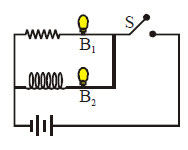
The adjoining figure shows two bulbs B1 and B2 resistor R and an inductor L. When the switch S is turned off :
The expression for magnetic induction inside a solenoid of length \(L\) carrying a current \(I\) and having \(N\) number of turns is:
Magnetic field inside a long solenoid is given by \(B = \mu_0 n I\), where \(n = \frac{N}{L}\) is the number of turns per unit length. Therefore, \(B = \mu_0 \frac{N}{L} I\).