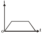
To plot a graph for the current
versus time
, let's break the problem into steps:
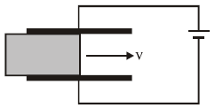
1. Capacitor with Dielectric Slab
2. Capacitance with Partial Dielectric
When a dielectric is partially inserted into the capacitor, the total capacitance is the sum of two capacitors:
- One part with the dielectric slab (
).
- One part without the dielectric slab (
).
Capacitance of the two regions:
- With Dielectric Slab:
where
is the dielectric constant.
- Without Dielectric Slab:
Thus, the total capacitance
is:
3. Change in Capacitance with Time
As the slab moves with speed
, the area covered by the slab changes with time:
The effective capacitance changes as:
Simplify:
4. Current in the Circuit
The current in the circuit is related to the rate of change of capacitance:
Differentiate
with respect to
:
Thus:
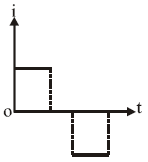
5. Graph of
vs.
The current
is constant because it does not depend on
(the rate of capacitance change is constant). Hence, the graph of
vs.
will be a horizontal line at: