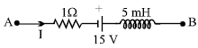
Two resistors of 10 W and 20 W and an ideal inductor of 10 H are connected to a 2 V battery
as shown. The key K is inserted at time t = 0. The initial (t = 0) and final (t →∞) currents
through battery are
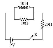
1. \[\frac{1}{15} A,\frac{1}{10} A\]
2. \[\frac{1}{10} A,\frac{1}{15} A\]
3. \[\frac{2}{15} A,\frac{1}{10} A\]
4. \[\frac{1}{15} A,\frac{2}{25} A\]
View Answer
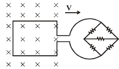
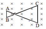
Using Lenz’s Law, determine the direction of current flow in the loop for each of the two
situations shown below.
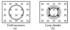
1. anticlockwise for (a) and Clockwise for (b)
2. clockwise for (a) and Clockwise for (b)
3. anticlockwise for (a) and Anticlockwise for (b)
4. clockwise for (a) and Anticlockwise for (b)
View Answer
Select the correct alternative. A thin semicircular conducting ring of radius R is falling with its plane vertical in a horizontal magnetic induction \[\overrightarrow{B}\] . At the position MNQ the speed of the ring is v & the potential difference developed across the ring is :
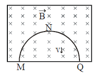
1. zero
2. BvπR²/2 & M is at higher potential
3. π RBV & Q is at higher potential
4. 2 RBV & Q is at higher potential
View Answer
A conducting rod AC of length 4l is rotated about a point O in a uniform magnetic field \[\overrightarrow{B}\] directed into the paper. AO = l and OC = 3l. Then
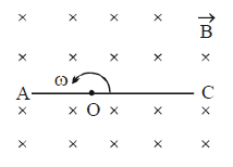
1. \[V_{A}-V_{0}=\frac{B\omega l^{2}}{2}\]
2. \[V_{0}-V_{C}=\frac{9}{2}B\omega l^{2}\]
3. \[V_{A}-V_{C}=8B\omega l^{2}\]
4. \[V_{C}-V_{0}=\frac{9}{2}B\omega l^{2}\]
View Answer
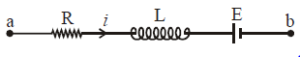
The figure shows three circuits with identical batteries, inductors, and resistors. Rank the circuits according to the current through the battery (i) just after the switch is closed and (ii) a long time later, greatest first :
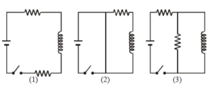
1. (i) i2 > i3 > i1 (i1 = 0) (ii) i2 > i3 > i1
2. (i) i2 < i3 > i1 (i1 ≠ 0) (ii) i2 > i3 > i1
3. (i) i2 = i3 = i1 (i1 = 0) (ii) i2 > i3 > i1
4. (i) i2 = i3 > i1 (i1 ≠ 0) (ii) i2 > i3 > i1
View Answer
(i) Just after the switch is closed (t = 0): An inductor opposes any sudden change in current. Initially, it acts like an infinite resistance (open circuit). No current can flow through any branch containing the inductor at this instant.
(ii) A long time later (t =infinity): Once the current reaches a steady state, the inductor no longer opposes the flow. It acts like an ideal wire (short circuit) with zero resistance. You can then rank the circuits by calculating the total equivalent resistance of the remaining resistors.