Parallel Plate Capacitor - NEET Physics Questions
← Back to Capacitors

Parallel Plate Capacitor

Question 11: moderate

A parallel plate capacitor of capacitance C consists of two identical plates A and B. A charge q is given to plate A and charge –q is given to plate B. The space between plates is vacuum. The separation between plates is d. The electric intensity at a point situated between plates is :

1. q/Cd
2. q/2Cd
3. 3q/2Cd
4. none of these
View Answer
Question 12: moderate

A parallel plate capacitor has plates of area A and separation d and is charged to a potential difference V. The charging battery is then disconnected and the plates are pulled apart until their separation is 2d. What is the work required to separated the plates?

1. \[2\varepsilon_{0}AV^{2}/d\]
2. \[\varepsilon_{0}AV^{2}/d\]
3. \[3\varepsilon_{0}AV^{2}/2d\]
4. \[\varepsilon_{0}AV^{2}/2d\]
View Answer

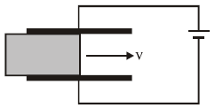
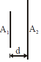
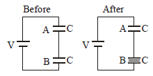
To calculate the work required to separate the plates of the capacitor, let’s analyze the situation step by step:


1. Initial Setup

  • The capacitor has:
    • Plate area =
      AA
       
    • Initial separation =
      dd
       
    • Initial potential difference =
      VV
       
  • After charging, the battery is disconnected, so the charge
    QQ
     

    on the plates remains constant.

The charge stored in the capacitor is given by:


Q=CVQ = C V


where

CC

is the capacitance:


C=ε0AdC = \frac{\varepsilon_0 A}{d}


Thus, the charge is:


Q=ε0AdVQ = \frac{\varepsilon_0 A}{d} V


2. Energy Stored in the Capacitor

The energy stored in the capacitor is:


U=12CV2U = \frac{1}{2} C V^2


Substituting

C=ε0AdC = \frac{\varepsilon_0 A}{d}

:


U=12ε0AdV2U = \frac{1}{2} \cdot \frac{\varepsilon_0 A}{d} \cdot V^2


Initially, the energy is:


Uinitial=ε0AV22dU_{\text{initial}} = \frac{\varepsilon_0 A V^2}{2d}


When the separation is increased to

2d2d

, the capacitance decreases to:


Cnew=ε0A2dC_{\text{new}} = \frac{\varepsilon_0 A}{2d}


The energy becomes:


Ufinal=12CnewVnew2U_{\text{final}} = \frac{1}{2} C_{\text{new}} V_{\text{new}}^2


Since the charge

QQ

is constant and

Q=CnewVnewQ = C_{\text{new}} V_{\text{new}}

:


Vnew=QCnew=ε0AdVε0A2d=2VV_{\text{new}} = \frac{Q}{C_{\text{new}}} = \frac{\frac{\varepsilon_0 A}{d} V}{\frac{\varepsilon_0 A}{2d}} = 2V


Substitute

CnewC_{\text{new}}

and

VnewV_{\text{new}}

:


Ufinal=12ε0A2d(2V)2U_{\text{final}} = \frac{1}{2} \cdot \frac{\varepsilon_0 A}{2d} \cdot (2V)^2


Ufinal=ε0AV22dU_{\text{final}} = \frac{\varepsilon_0 A V^2}{2d}


3. Work Done to Separate the Plates

The work done to separate the plates is equal to the increase in energy:


W=UfinalUinitialW = U_{\text{final}} - U_{\text{initial}}


Substitute the values:


W=ε0AV22dε0AV22dW = \frac{\varepsilon_0 A V^2}{2d} - \frac{\varepsilon_0 A V^2}{2d}


W=ε0AV22dW = \frac{\varepsilon_0 A V^2}{2d}


Final Answer:

The work required to separate the plates is:


W=ε0AV22dW = \frac{\varepsilon_0 A V^2}{2d}


Question 13: moderate

Ten capacitors are joined in parallel and charged with a battery up to a potential V. They are then disconnected from the battery and joined in series. Then, the potential of this combination will be:

1. 1 V
2. 10 V
3. 5 V
4. 2 V
View Answer

Let's analyze the problem step by step and derive why the potential difference is 10 V.


1. Capacitors in Parallel (Initial Condition)

When the 10 capacitors, each with capacitance

CC

, are connected in parallel:

  • The equivalent capacitance is:
    Cparallel=10CC_{\text{parallel}} = 10C
     
  • The total charge stored when connected to a battery of potential
    VV
     

    is: Q=CparallelV=(10C)V=10CVQ = C_{\text{parallel}} \cdot V = (10C) \cdot V = 10CV 


2. Capacitors in Series (Reconfigured System)

After disconnecting the battery, the capacitors are joined in series:

  • The equivalent capacitance for 10 capacitors in series is:
    Cseries=C10C_{\text{series}} = \frac{C}{10}
     
  • The charge
    QQ
     

    stored on the series combination remains the same (as charge is conserved): Qseries=Q=10CVQ_{\text{series}} = Q = 10CV 


3. Potential Across the Series Combination

The potential difference across a capacitor or combination of capacitors is related to the charge

QQ

and capacitance

CC

:


Vseries=QCseriesV_{\text{series}} = \frac{Q}{C_{\text{series}}}


Substitute

Q=10CVQ = 10CV

and

Cseries=C10C_{\text{series}} = \frac{C}{10}

:


Vseries=10CVC10=VV_{\text{series}} = \frac{10CV}{\frac{C}{10}} = V


Thus, the potential across the series combination is

V=10VV = 10V

,.


Final Answer:

The potential of the series combination is:


10V\boxed{10V}


Question 14: difficult

A dielectric slab of area A is inserted between the plates of a capacitor of area 2A with constant speed v as shown in figure. Distance between the plates is d.

The capacitor is connected to a battery of emf E. The current in the circuit varies with time as

1.
2.
3.
4.
View Answer

To plot a graph for the current

ii

versus time

tt

, let's break the problem into steps:


1. Capacitor with Dielectric Slab

  • Initial Configuration: The capacitor has plates of total area
    2A2A
     

    and plate separation dd 

    . It is connected to a battery with emf EE 

    .

  • Dielectric Slab: A dielectric slab of area
    AA
     

    is inserted at a constant speed vv 

    .


2. Capacitance with Partial Dielectric

When a dielectric is partially inserted into the capacitor, the total capacitance is the sum of two capacitors:

  • One part with the dielectric slab (
    C1C_1
     

    ).

  • One part without the dielectric slab (
    C2C_2
     

    ).

Capacitance of the two regions:

  1. With Dielectric Slab: 

    C1=κε0AdC_1 = \frac{\kappa \varepsilon_0 A}{d}where

    κ\kappais the dielectric constant.

  2. Without Dielectric Slab: 

    C2=ε0(2AA)d=ε0AdC_2 = \frac{\varepsilon_0 (2A - A)}{d} = \frac{\varepsilon_0 A}{d} 

Thus, the total capacitance

CtotalC_{\text{total}}

is:


Ctotal=C1+C2=κε0Ad+ε0AdC_{\text{total}} = C_1 + C_2 = \frac{\kappa \varepsilon_0 A}{d} + \frac{\varepsilon_0 A}{d}


Ctotal=ε0Ad(κ+1)C_{\text{total}} = \frac{\varepsilon_0 A}{d} (\kappa + 1)


3. Change in Capacitance with Time

As the slab moves with speed

vv

, the area covered by the slab changes with time:


Covered area Acovered=vt\text{Covered area } A_{\text{covered}} = v \cdot t


The effective capacitance changes as:


C(t)=κε0(vt)d+ε0(2Avt)dC(t) = \frac{\kappa \varepsilon_0 (v \cdot t)}{d} + \frac{\varepsilon_0 (2A - v \cdot t)}{d}


C(t)=ε0d[κ(vt)+(2Avt)]C(t) = \frac{\varepsilon_0}{d} \left[ \kappa (v \cdot t) + (2A - v \cdot t) \right]


Simplify:


C(t)=ε0d[2A+(κ1)(vt)]C(t) = \frac{\varepsilon_0}{d} \left[ 2A + (\kappa - 1)(v \cdot t) \right]


4. Current in the Circuit

The current in the circuit is related to the rate of change of capacitance:


i(t)=EdCdti(t) = E \cdot \frac{dC}{dt}


Differentiate

C(t)C(t)

with respect to

tt

:


dCdt=ε0d(κ1)v\frac{dC}{dt} = \frac{\varepsilon_0}{d} (\kappa - 1) v


Thus:


i(t)=Eε0d(κ1)vi(t) = E \cdot \frac{\varepsilon_0}{d} (\kappa - 1) v


5. Graph of ii


vs. tt


The current

i(t)i(t)

is constant because it does not depend on

tt

(the rate of capacitance change is constant). Hence, the graph of

ii

vs.

tt

will be a horizontal line at:


i=Eε0d(κ1)vi = E \cdot \frac{\varepsilon_0}{d} (\kappa - 1) v


Question 15: difficult

Plates of area A are arranged as shown. The distance between each plate is d, the net capacitance is :

1. \[\frac{\varepsilon_{0}A}{d}\]
2. \[\frac{7\varepsilon_{0}A}{d}\]
3. \[\frac{6\varepsilon_{0}A}{d}\]
4. \[\frac{5\varepsilon_{0}A}{d}\]
View Answer

The arrangement appears to be a system of parallel plates connected alternately to terminals

aa

and

bb

. Let’s determine the net capacitance.

Key Observations:

  1. The plates form a series-parallel combination.
  2. The area of each plate is
    AA
     

    , and the separation between adjacent plates is dd 

    .

  3. The effective configuration can be reduced to find the equivalent capacitance.

Equivalent Capacitance Derivation:

  1. Pairing of Plates:
    • Adjacent plates (connected alternately) act as capacitors.
    • Each capacitor has a capacitance
      C=ε0AdC = \frac{\varepsilon_0 A}{d}
       

      .

  2. Parallel and Series Combination:
    • There are three capacitors in the arrangement, effectively forming a single network.
    • The middle plate shares equal charge with both sides, simplifying to an equivalent capacitance of
      ε0Ad\frac{\varepsilon_0 A}{d}
       

      .

Thus, the net capacitance is:


Cnet=ε0Ad.C_{\text{net}} = \frac{\varepsilon_0 A}{d}.


Question 16: easy

A capacitor is charged by a battery and the energy stored is U. The battery is now removed and the separation distance between the plates is doubled. The energy stored now is :

1. U/2
2. U
3. 2U
4. 4U
View Answer

Let’s solve step by step why the energy stored becomes

2U2U

:


1. Initial Setup

  • Capacitance of the capacitor: 

    C=ε0AdC = \frac{\varepsilon_0 A}{d}where:


    • AA
       

      = area of the plates,


    • dd
       

      = distance between the plates,


    • ε0\varepsilon_0
       

      = permittivity of free space.

  • When the capacitor is charged by a battery to a voltage
    VV
     

    , the charge stored is: 

    Q=CVQ = CVThe energy stored in the capacitor is:


    U=12CV2U = \frac{1}{2} C V^2 


2. When the Distance is Doubled

After the battery is removed, the charge

QQ

on the capacitor remains constant because there’s no external connection. However, the capacitance changes due to the increased plate separation.

  • New capacitance: 

    C=ε0A2dC' = \frac{\varepsilon_0 A}{2d} 

  • Energy stored in a capacitor is given by: 

    U=Q22CU' = \frac{Q^2}{2C'}Substitute

    C=ε0A2dC' = \frac{\varepsilon_0 A}{2d}:


    U=Q22ε0A2d=Q22d2ε0AU' = \frac{Q^2}{2 \cdot \frac{\varepsilon_0 A}{2d}} = \frac{Q^2 \cdot 2d}{2 \varepsilon_0 A}Simplify:


    U=Q2dε0AU' = \frac{Q^2 d}{\varepsilon_0 A} 


3. Relating UU'


and UU


From the initial setup:


U=12CV2U = \frac{1}{2} C V^2


Substitute

C=ε0AdC = \frac{\varepsilon_0 A}{d}

and

Q=CVQ = CV

:


U=12ε0AdV2=Q22CU = \frac{1}{2} \cdot \frac{\varepsilon_0 A}{d} \cdot V^2 = \frac{Q^2}{2C}


From the doubling of plate separation:


U=2Q22C=2UU' = 2 \cdot \frac{Q^2}{2C} = 2U


Final Answer:

The energy stored in the capacitor after doubling the separation is:


2U\boxed{2U}


Question 17: moderate

A 2μF capacitor is charged as shown in figure. The percentage of its stored energy dissiplated
after the switch S is turned to position 2 is :

1. 0%
2. 20%
3. 75%
4. 80%
View Answer

To solve this, let's calculate the percentage of energy dissipated when the switch

SS

is turned to position 2.

Given:


  • C1=2μFC_1 = 2 \, \mu\text{F}
     

  • C2=8μFC_2 = 8 \, \mu\text{F}
     
  • Initial voltage across
    C1=VC_1 = V
     

Key Concept:

When two capacitors are connected, the redistribution of charge causes energy loss. The energy dissipated can be calculated using the direct formula:


Energy dissipated=12C1C2C1+C2(V1V2)2\text{Energy dissipated} = \frac{1}{2} \frac{C_1 C_2}{C_1 + C_2} (V_1 - V_2)^2


Here:


  • V1V_1
     

    is the initial voltage of C1C_1 

    .


  • V2=0V_2 = 0
     

    (initially, C2C_2 

    is uncharged).

Step-by-step Calculation:

  1. Common Voltage after Connection: The final voltage across both capacitors is: 

    Vcommon=C1VC1+C2=2V2+8=V5.V_{\text{common}} = \frac{C_1 V}{C_1 + C_2} = \frac{2V}{2 + 8} = \frac{V}{5}. 

  2. Initial Energy Stored in
    C1C_1
     

    : 

    Einitial=12C1V2=12(2×10⁶)V2=106V2J.E_{\text{initial}} = \frac{1}{2} C_1 V^2 = \frac{1}{2} (2 \times 10^{-6}) V^2 = 10^{-6} V^2 \, \text{J}. 

  3. Final Energy Stored: The total energy stored after redistribution is: 

    Efinal=12(C1+C2)Vcommon2=12(2+8)(V5)2.E_{\text{final}} = \frac{1}{2} (C_1 + C_2) V_{\text{common}}^2 = \frac{1}{2} (2 + 8) \left(\frac{V}{5}\right)^2.Substituting values:


    Efinal=12(10)(V225)=10V250=V25×106J.E_{\text{final}} = \frac{1}{2} (10) \left(\frac{V^2}{25}\right) = \frac{10 V^2}{50} = \frac{V^2}{5} \times 10^{-6} \, \text{J}. 

  4. Energy Dissipated: 

    Edissipated=EinitialEfinal=106V2106V25=45×106V2.E_{\text{dissipated}} = E_{\text{initial}} - E_{\text{final}} = 10^{-6} V^2 - \frac{10^{-6} V^2}{5} = \frac{4}{5} \times 10^{-6} V^2. 

  5. Percentage of Energy Dissipated: 

    %Dissipated=EdissipatedEinitial×100=45×106V2106V2×100=80%.\% \text{Dissipated} = \frac{E_{\text{dissipated}}}{E_{\text{initial}}} \times 100 = \frac{\frac{4}{5} \times 10^{-6} V^2}{10^{-6} V^2} \times 100 = 80\%. 

Final Answer:

The percentage of energy dissipated is 80%.

Question 18: moderate

The capacitance of capacitor of plate areas A1 and A2 (A1 < A2) at a distance d is :

1. \[\frac{\varepsilon_{0}A_{1}}{d}\]
2. \[\frac{\varepsilon_{0}A_{2}}{d}\]
3. \[\frac{\varepsilon_{0}\left( A_{1}+A_{2} \right)}{2d}\]
4. \[\frac{\varepsilon_{0}\sqrt{A_{1}A_{2}}}{d}\]
View Answer

The capacitance of a parallel-plate capacitor is given by the general formula:


C=ε0AdC = \frac{\varepsilon_0 A}{d}


where:


  • CC
     

    = capacitance,


  • ε0\varepsilon_0
     

    = permittivity of free space,


  • AA
     

    = effective overlapping area of the two plates,


  • dd
     

    = separation between the plates.


For Plates of Unequal Areas ( A1<A2A_1 < A_2


):

When two plates of areas

A1A_1

and

A2A_2

are used to form a capacitor, only the smaller area (

A1A_1

) determines the effective overlapping area for charge storage. This is because the excess area of the larger plate (

A2A1A_2 - A_1

) does not contribute to the capacitance.

Thus, the capacitance is:


C=ε0A1dC = \frac{\varepsilon_0 A_1}{d}


Final Answer:

The capacitance of the capacitor is:


C=ε0A1d\boxed{C = \frac{\varepsilon_0 A_1}{d}}


Question 19: easy

Two identical capacitors are connected in series as shown in the figure. A dielectric slab ( K > 1) is placed between the plates of the capacitor B and the battery remains connected. Select correct statement


1. The charge supplied by the battery increases.
2. The capacitance of the system decreases
3. The electric field in the capacitor B increases.
4. The electrostatic potential energy decreases.
View Answer

On inserting dielectric Capacitance of the system increases so more charge is given by the battery.

Question 20: moderate

A capacitor of capacitance 1μF and charge 1μC is connected to a 2μF capacitor charged to 4 μC with the terminals of unlike sign together. The final charge on the two capacitors is

1. 1/3 μC and 1/3 μC
2. 1 μC and 2 μC
3. 1/3 μC and 1 μC
4. 2/3 μC and 2/3 μC
View Answer

Let's solve this using the direct formula.

Formula:

The final common voltage

VV

across the capacitors after they are connected is given by:


V=C1V1C2V2C1+C2V = \frac{C_1 V_1 - C_2 V_2}{C_1 + C_2}


Step 1: Given Data


  • C1=1μF,Q1=1μCV1=Q1C1=11=1VC_1 = 1 \, \mu\text{F}, \, Q_1 = 1 \, \mu\text{C} \Rightarrow V_1 = \frac{Q_1}{C_1} = \frac{1}{1} = 1 \, \text{V}
     

  • C2=2μF,Q2=4μCV2=Q2C2=42=2VC_2 = 2 \, \mu\text{F}, \, Q_2 = 4 \, \mu\text{C} \Rightarrow V_2 = \frac{Q_2}{C_2} = \frac{4}{2} = 2 \, \text{V}
     

Step 2: Final Voltage

Substitute into the formula:


V=C1V1C2V2C1+C2=11221+2=143=33=1V.V = \frac{C_1 V_1 - C_2 V_2}{C_1 + C_2} = \frac{1 \cdot 1 - 2 \cdot 2}{1 + 2} = \frac{1 - 4}{3} = \frac{-3}{3} = -1 \, \text{V}.


(Note: The negative sign indicates the direction of potential difference.)

Step 3: Final Charges

The final charges on the capacitors are calculated using

Q=CVQ = C \cdot V

:

  • For
    C1C_1
     

    : Q1=C1V=1(1)=1μCQ_1' = C_1 \cdot V = 1 \cdot (-1) = -1 \, \mu\text{C} 

    , but in magnitude, Q1=1μCQ_1' = 1 \, \mu\text{C} 

    .

  • For
    C2C_2
     

    : Q2=C2V=2(1)=2μCQ_2' = C_2 \cdot V = 2 \cdot (-1) = -2 \, \mu\text{C} 

    , but in magnitude, Q2=2μCQ_2' = 2 \, \mu\text{C} 

    .


Final Answer:

The final charges are:


1μCand2μC.\boxed{1 \, \mu\text{C} \, \text{and} \, 2 \, \mu\text{C}}.