Capacitors - NEET Physics Questions
Question 41: moderate

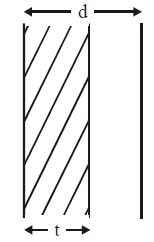
A parallel plate capacitor with air between the plates has a capacitance of 9 pF. The separation between its plates is ‘d’. The space between the plates is now filled with two dielectrics. One of the dielectrics has dielectric constant k1 = 3 and thickness d/3 while the other one has dielectric constant k2 = 6 and thickness 2d/3. Capacitance of the capacitor is now :

1. 45 pF
2. 40.5 pF
3. 20.25 pF
4. 1.8 pF
View Answer

Given:

  • Initial capacitance with air as the dielectric:
    C=9pFC = 9 \, \text{pF}
     
  • Dielectric constants:
    k1=3k_1 = 3
     

    , k2=6k_2 = 6 

  • Thicknesses of the dielectrics:
    d1=d3d_1 = \frac{d}{3}
     

    and d2=2d3d_2 = \frac{2d}{3} 

Step-by-step solution:

1. Capacitance formula:

The capacitance of a parallel plate capacitor is:


C=kε0AdC = \frac{k \varepsilon_0 A}{d}


Where:


  • kk
     

    is the dielectric constant,


  • ε0\varepsilon_0
     

    is the permittivity of free space,


  • AA
     

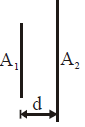
    is the area of the plates,


  • dd
     

    is the separation between the plates.

When we insert dielectrics in series, we treat the system as two capacitors in series with different dielectric constants.

2. Capacitance of each section:

  • For the dielectric with
    k1=3k_1 = 3
     

    and thickness d1=d3d_1 = \frac{d}{3} 

    , the capacitance C1C_1 

    is:


C1=k1ε0Ad1=3ε0Ad/3=9ε0AdC_1 = \frac{k_1 \varepsilon_0 A}{d_1} = \frac{3 \varepsilon_0 A}{d/3} = \frac{9 \varepsilon_0 A}{d}


  • For the dielectric with
    k2=6k_2 = 6
     

    and thickness d2=2d3d_2 = \frac{2d}{3} 

    , the capacitance C2C_2 

    is:


C2=k2ε0Ad2=6ε0A2d/3=9ε0AdC_2 = \frac{k_2 \varepsilon_0 A}{d_2} = \frac{6 \varepsilon_0 A}{2d/3} = \frac{9 \varepsilon_0 A}{d}


3. Total capacitance:

The total capacitance of the system is found by treating the two capacitances in series. For capacitors in series, the total capacitance

CtotalC_{\text{total}}

is given by:


1Ctotal=1C1+1C2\frac{1}{C_{\text{total}}} = \frac{1}{C_1} + \frac{1}{C_2}


Substitute

C1=C2=9ε0AdC_1 = C_2 = \frac{9 \varepsilon_0 A}{d}

:


1Ctotal=19ε0Ad+19ε0Ad=29ε0Ad\frac{1}{C_{\text{total}}} = \frac{1}{\frac{9 \varepsilon_0 A}{d}} + \frac{1}{\frac{9 \varepsilon_0 A}{d}} = \frac{2}{\frac{9 \varepsilon_0 A}{d}}


Thus,


Ctotal=9ε0A2dC_{\text{total}} = \frac{9 \varepsilon_0 A}{2d}


4. Relating to the original capacitance:

The original capacitance with air as the dielectric is:


C=ε0AdC = \frac{\varepsilon_0 A}{d}


Therefore, the total capacitance becomes:


Ctotal=92C=4.5C=4.5×9pF=40.5pFC_{\text{total}} = \frac{9}{2} C = 4.5 C = 4.5 \times 9 \, \text{pF} = 40.5 \, \text{pF}


Final Answer:

The total capacitance with the two dielectrics is 40.5 pF.

Thus, 40.5 pF is the correct answer.

Question 42: moderate

A 2μF capacitor is charged as shown in figure. The percentage of its stored energy dissiplated
after the switch S is turned to position 2 is :

1. 0%
2. 20%
3. 75%
4. 80%
View Answer

To solve this, let's calculate the percentage of energy dissipated when the switch

SS

is turned to position 2.

Given:


  • C1=2μFC_1 = 2 \, \mu\text{F}
     

  • C2=8μFC_2 = 8 \, \mu\text{F}
     
  • Initial voltage across
    C1=VC_1 = V
     

Key Concept:

When two capacitors are connected, the redistribution of charge causes energy loss. The energy dissipated can be calculated using the direct formula:


Energy dissipated=12C1C2C1+C2(V1V2)2\text{Energy dissipated} = \frac{1}{2} \frac{C_1 C_2}{C_1 + C_2} (V_1 - V_2)^2


Here:


  • V1V_1
     

    is the initial voltage of C1C_1 

    .


  • V2=0V_2 = 0
     

    (initially, C2C_2 

    is uncharged).

Step-by-step Calculation:

  1. Common Voltage after Connection: The final voltage across both capacitors is: 

    Vcommon=C1VC1+C2=2V2+8=V5.V_{\text{common}} = \frac{C_1 V}{C_1 + C_2} = \frac{2V}{2 + 8} = \frac{V}{5}. 

  2. Initial Energy Stored in
    C1C_1
     

    : 

    Einitial=12C1V2=12(2×10⁶)V2=106V2J.E_{\text{initial}} = \frac{1}{2} C_1 V^2 = \frac{1}{2} (2 \times 10^{-6}) V^2 = 10^{-6} V^2 \, \text{J}. 

  3. Final Energy Stored: The total energy stored after redistribution is: 

    Efinal=12(C1+C2)Vcommon2=12(2+8)(V5)2.E_{\text{final}} = \frac{1}{2} (C_1 + C_2) V_{\text{common}}^2 = \frac{1}{2} (2 + 8) \left(\frac{V}{5}\right)^2.Substituting values:


    Efinal=12(10)(V225)=10V250=V25×106J.E_{\text{final}} = \frac{1}{2} (10) \left(\frac{V^2}{25}\right) = \frac{10 V^2}{50} = \frac{V^2}{5} \times 10^{-6} \, \text{J}. 

  4. Energy Dissipated: 

    Edissipated=EinitialEfinal=106V2106V25=45×106V2.E_{\text{dissipated}} = E_{\text{initial}} - E_{\text{final}} = 10^{-6} V^2 - \frac{10^{-6} V^2}{5} = \frac{4}{5} \times 10^{-6} V^2. 

  5. Percentage of Energy Dissipated: 

    %Dissipated=EdissipatedEinitial×100=45×106V2106V2×100=80%.\% \text{Dissipated} = \frac{E_{\text{dissipated}}}{E_{\text{initial}}} \times 100 = \frac{\frac{4}{5} \times 10^{-6} V^2}{10^{-6} V^2} \times 100 = 80\%. 

Final Answer:

The percentage of energy dissipated is 80%.

Question 43: moderate

An isolated parallel-plate capacitor consists of two metal plates of area A and separation d. A slab of thickness t and dielectric constant K = 2 is inserted between the plates with its faces parallel to the plates and having the same surface area as that of the plates as shown

The capacitance of the system is :


1. \[\frac{\varepsilon_{0}A}{\left( d-\frac{t}{2} \right)}\]
2. \[\frac{\varepsilon_{0}A}{\left( d+\frac{t}{2} \right)}\]
3. \[\frac{\varepsilon_{0}A}{d-t}\]
4. \[\frac{\varepsilon_{0}A}{d+t}\]
View Answer

The question involves calculating the capacitance of a parallel-plate capacitor when a dielectric slab of thickness

tt

and dielectric constant

K=2K = 2

is partially inserted between the plates.

The short solution is based on treating the system as a combination of two capacitors in series:

  1. Capacitor 1 (region with dielectric): The thickness of this region is
    tt
     

    , and the capacitance is given by: 

    C1=ε0AKt=2ε0AtC_1 = \frac{\varepsilon_0 A K}{t} = \frac{2\varepsilon_0 A}{t} 

  2. Capacitor 2 (region without dielectric): The thickness of this region is
    dtd - t
     

    , and the capacitance is: 

    C2=ε0AdtC_2 = \frac{\varepsilon_0 A}{d - t} 

Since the two regions are in series, the equivalent capacitance is given by:


1C=1C1+1C2\frac{1}{C} = \frac{1}{C_1} + \frac{1}{C_2}


Substituting

C1C_1

and

C2C_2

:


1C=t2ε0A+dtε0A\frac{1}{C} = \frac{t}{2\varepsilon_0 A} + \frac{d - t}{\varepsilon_0 A}


Simplifying:


1C=t+2(dt)2ε0A=2dt2ε0A\frac{1}{C} = \frac{t + 2(d - t)}{2\varepsilon_0 A} = \frac{2d - t}{2\varepsilon_0 A}


Therefore:


C=2ε0A2dtC = \frac{2\varepsilon_0 A}{2d - t}


When the dielectric slab thickness is

t=d2t = \frac{d}{2}

, the capacitance simplifies to:


C=ε0Adt2C = \frac{\varepsilon_0 A}{d - \frac{t}{2}}


This matches the given answer. Let me know if further clarification is needed!

Question 44: moderate

The capacitance of capacitor of plate areas A1 and A2 (A1 < A2) at a distance d is :

1. \[\frac{\varepsilon_{0}A_{1}}{d}\]
2. \[\frac{\varepsilon_{0}A_{2}}{d}\]
3. \[\frac{\varepsilon_{0}\left( A_{1}+A_{2} \right)}{2d}\]
4. \[\frac{\varepsilon_{0}\sqrt{A_{1}A_{2}}}{d}\]
View Answer

The capacitance of a parallel-plate capacitor is given by the general formula:


C=ε0AdC = \frac{\varepsilon_0 A}{d}


where:


  • CC
     

    = capacitance,


  • ε0\varepsilon_0
     

    = permittivity of free space,


  • AA
     

    = effective overlapping area of the two plates,


  • dd
     

    = separation between the plates.


For Plates of Unequal Areas ( A1<A2A_1 < A_2


):

When two plates of areas

A1A_1

and

A2A_2

are used to form a capacitor, only the smaller area (

A1A_1

) determines the effective overlapping area for charge storage. This is because the excess area of the larger plate (

A2A1A_2 - A_1

) does not contribute to the capacitance.

Thus, the capacitance is:


C=ε0A1dC = \frac{\varepsilon_0 A_1}{d}


Final Answer:

The capacitance of the capacitor is:


C=ε0A1d\boxed{C = \frac{\varepsilon_0 A_1}{d}}


Question 45: difficult

A capacitor is charged from a cell with the help of a resistor. The circuit has a time constant τ. The capacitor collects 10% of the steady charge at time t given by :

1. τln(1.1)
2. τ ln (10/9)
3. τ ln (0.9)
4. τ ln (0.1)
View Answer

The charging of a capacitor through a resistor is described by the following equation:


Q(t)=Qmax(1et/τ)Q(t) = Q_{\text{max}} \left( 1 - e^{-t/\tau} \right)


Where:


  • Q(t)Q(t)
     

    is the charge on the capacitor at time tt 

    ,


  • QmaxQ_{\text{max}}
     

    is the maximum (steady-state) charge the capacitor can hold,


  • τ\tau
     

    is the time constant, τ=RC\tau = R \cdot C 

    , where RR 

    is the resistance and CC 

    is the capacitance,


  • tt
     

    is the time.

Step 1: Given condition (10% of steady charge)

We are told that at time

tt

, the capacitor has collected 10% of the steady charge, so:


Q(t)=0.1QmaxQ(t) = 0.1 \cdot Q_{\text{max}}


Step 2: Substitute into the charging equation

Substitute

Q(t)=0.1QmaxQ(t) = 0.1 \cdot Q_{\text{max}}

into the charging formula:


0.1Qmax=Qmax(1et/τ)0.1 \cdot Q_{\text{max}} = Q_{\text{max}} \left( 1 - e^{-t/\tau} \right)


Cancel

QmaxQ_{\text{max}}

from both sides:


0.1=1et/τ0.1 = 1 - e^{-t/\tau}


Step 3: Solve for tt


Rearrange the equation to solve for

et/τe^{-t/\tau}

:


et/τ=10.1=0.9e^{-t/\tau} = 1 - 0.1 = 0.9


Take the natural logarithm of both sides:


tτ=ln(0.9)-\frac{t}{\tau} = \ln(0.9)


t=τln(0.9)t = -\tau \ln(0.9)


Using the fact that

ln(0.9)=ln(10/9)\ln(0.9) = -\ln(10/9)

:


t=τln(109)t = \tau \ln\left(\frac{10}{9}\right)


Final Answer:

The time at which the capacitor has collected 10% of the steady charge is

t=τln(109)t = \tau \ln\left(\frac{10}{9}\right)

.

Question 46: moderate

Calculate the charge on the second capacitor before and after switch in the circuit is closed :

1. CE/2, CE
2. 0, 0
3. 0, CE
4. CE, 0
View Answer

When Switch is Open Equivalent Capacitance is Ceq=C/2

So, Charge on Both the capacitors in CE/2.

When Switch is Closed 1st Capacitor is short circuited .Now  Equivalent Capacitance is Ceq=C.

So, Charge on  the capacitors in CE.


Question 47: easy

The equivalent capacitance of the combination shown in figure is :

1. C
2. 2C
3. 3/2
4. C/2
View Answer


Reason for the Short Circuit:

The middle capacitor is bypassed by a conducting wire (short circuit). Hence, no voltage difference exists across the middle capacitor, and it can be ignored in the calculation.


Simplified Circuit:

  1. The circuit reduces to two capacitors
    CC
     

    at the top and bottom in parallel.

  2. For capacitors in parallel, the equivalent capacitance is simply the sum of their capacitances:
    Ceq=C+C=2CC_{\text{eq}} = C + C = 2C
     

Final Answer:

The equivalent capacitance of the given combination is 2C.

Question 48: easy

Two identical capacitors are connected in series as shown in the figure. A dielectric slab ( K > 1) is placed between the plates of the capacitor B and the battery remains connected. Select correct statement


1. The charge supplied by the battery increases.
2. The capacitance of the system decreases
3. The electric field in the capacitor B increases.
4. The electrostatic potential energy decreases.
View Answer

On inserting dielectric Capacitance of the system increases so more charge is given by the battery.

Question 49: moderate

A capacitor of capacitance 1μF and charge 1μC is connected to a 2μF capacitor charged to 4 μC with the terminals of unlike sign together. The final charge on the two capacitors is

1. 1/3 μC and 1/3 μC
2. 1 μC and 2 μC
3. 1/3 μC and 1 μC
4. 2/3 μC and 2/3 μC
View Answer

Let's solve this using the direct formula.

Formula:

The final common voltage

VV

across the capacitors after they are connected is given by:


V=C1V1C2V2C1+C2V = \frac{C_1 V_1 - C_2 V_2}{C_1 + C_2}


Step 1: Given Data


  • C1=1μF,Q1=1μCV1=Q1C1=11=1VC_1 = 1 \, \mu\text{F}, \, Q_1 = 1 \, \mu\text{C} \Rightarrow V_1 = \frac{Q_1}{C_1} = \frac{1}{1} = 1 \, \text{V}
     

  • C2=2μF,Q2=4μCV2=Q2C2=42=2VC_2 = 2 \, \mu\text{F}, \, Q_2 = 4 \, \mu\text{C} \Rightarrow V_2 = \frac{Q_2}{C_2} = \frac{4}{2} = 2 \, \text{V}
     

Step 2: Final Voltage

Substitute into the formula:


V=C1V1C2V2C1+C2=11221+2=143=33=1V.V = \frac{C_1 V_1 - C_2 V_2}{C_1 + C_2} = \frac{1 \cdot 1 - 2 \cdot 2}{1 + 2} = \frac{1 - 4}{3} = \frac{-3}{3} = -1 \, \text{V}.


(Note: The negative sign indicates the direction of potential difference.)

Step 3: Final Charges

The final charges on the capacitors are calculated using

Q=CVQ = C \cdot V

:

  • For
    C1C_1
     

    : Q1=C1V=1(1)=1μCQ_1' = C_1 \cdot V = 1 \cdot (-1) = -1 \, \mu\text{C} 

    , but in magnitude, Q1=1μCQ_1' = 1 \, \mu\text{C} 

    .

  • For
    C2C_2
     

    : Q2=C2V=2(1)=2μCQ_2' = C_2 \cdot V = 2 \cdot (-1) = -2 \, \mu\text{C} 

    , but in magnitude, Q2=2μCQ_2' = 2 \, \mu\text{C} 

    .


Final Answer:

The final charges are:


1μCand2μC.\boxed{1 \, \mu\text{C} \, \text{and} \, 2 \, \mu\text{C}}.


Question 50: moderate

A parallel plate air capacitor of capacitance C is connected to a cell of emf V and then disconnected from it. A dielectric slab of dielectric constant K, which can just fill the air gap of the capacitor, is now inserted in it. Which of the following is incorrect ?

1. The energy stored in the capacitor decreases K times
2. The change in energy stored is \( \frac{1}{2}CV^{2}\left( \frac{1}{K}-1 \right)\)
3. The charge on the capacitor is not conserved
4. The potential difference between the plates decreases K times.
View Answer

The incorrect statement is "The charge on the capacitor is not conserved".

Here’s the explanation:

  1. Initially, when the capacitor is connected to the battery with emf
    VV
     

    , it stores a charge

    Qinitial=C×VQ_{\text{initial}} = C \times V 

    , where

    CC 

    is the capacitance of the air capacitor.

  2. After disconnecting the capacitor from the battery, the charge on the capacitor is conserved because the capacitor is isolated. No charge can flow in or out.
  3. When the dielectric slab of dielectric constant
    KK
     

    is inserted, the capacitance of the capacitor increases to

    K×CK \times C 

    , but the charge remains the same because the capacitor is disconnected from the battery. The charge is now distributed on the new capacitance, and the voltage across the plates decreases.

  4. The statement "charge is not conserved" is incorrect because charge is conserved in this isolated system. The only change is in the voltage across the capacitor due to the increased capacitance.

Thus, charge on the capacitor is conserved and the incorrect statement is the one claiming otherwise.