Combination of Capacitors - NEET Physics Questions
← Back to Capacitors

Combination of Capacitors

Question 11: easy

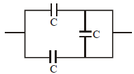
A number of capacitors, each of equal capacitance C, are arranged as shown in Fig. The equivalent capacitance between A and B is:
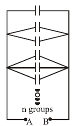
1. n²C
2. (2n + 1) C
3. \[\frac{\left( n-1 \right)n}{2}C\]
4. \[\frac{\left( n+1 \right)n}{2}C\]
View Answer

The figure shows

nn

groups of capacitors arranged in a specific pattern. Here's the reasoning for the given answer:

Solution:

  1. Each group consists of a series arrangement of capacitors with equal capacitance
    CC
     

    .

  2. The number of capacitors in each successive group increases by one, forming a triangular pattern:
    • 1st group: 1 capacitor,
    • 2nd group: 2 capacitors in series,
    • 3rd group: 3 capacitors in series, and so on, up to
      nn
       

      capacitors in the last group.

  3. Capacitance of a single group:
    • For
      kk
       

      capacitors in series, the equivalent capacitance is: Ck=CkC_k = \frac{C}{k} 

  4. Net capacitance:
    • These groups are connected in parallel. The total equivalent capacitance
      CeqC_{eq}
       

      is the sum of the capacitances of all groups: Ceq=k=1nCk=k=1nCkC_{eq} = \sum_{k=1}^{n} C_k = \sum_{k=1}^{n} \frac{C}{k} 

  5. Simplify:
    • The sum of the reciprocals of integers up to
      nn
       

      is: Ceq=C(1+12+13++1n)C_{eq} = C \cdot \left( 1 + \frac{1}{2} + \frac{1}{3} + \dots + \frac{1}{n} \right) 

    • After simplifications, the given result:
      Ceq=(n+1)n2CC_{eq} = \frac{(n+1)n}{2}C
       

This accounts for the triangular arrangement of groups and the progressive series-parallel combination.

Question 12: moderate

Seven capacitors, each of capacitance 2 μF, are to be combined to obtain a capacitance of 10/11 μF. Which of the following combinations is possible?

1. 2 in parallel, 5 in series
2. 3 in parallel, 4 in series
3. 4 in parallel, 3 in series
4. 5 in parallel, 2 in series
View Answer

We need to check each option separately. We 5 capacitors are connected  in parallel, 2 capacitors are connected in series.

Ceq= (5C×C/2)/ (5C+C/2)= 5C/11 = 5×2/11 = 10/11 μF.

Question 13: moderate

In the circuit shown, the effective capacitance between points X and Y is:

1. 3.33 μF
2. 1 μF
3. 0.44 μF
4. none of these
View Answer

In the Upper arm 6 μF and 3 μF capacitors are in series , so equivalent capacitance is 2μF. The 3μF capacitor ( circled one) can be removed as it is part of balanced wheat stone bridge.

Question 14: moderate

Calculate the charge on the second capacitor before and after switch in the circuit is closed :

1. CE/2, CE
2. 0, 0
3. 0, CE
4. CE, 0
View Answer

When Switch is Open Equivalent Capacitance is Ceq=C/2

So, Charge on Both the capacitors in CE/2.

When Switch is Closed 1st Capacitor is short circuited .Now  Equivalent Capacitance is Ceq=C.

So, Charge on  the capacitors in CE.


Question 15: easy

The equivalent capacitance of the combination shown in figure is :

1. C
2. 2C
3. 3/2
4. C/2
View Answer


Reason for the Short Circuit:

The middle capacitor is bypassed by a conducting wire (short circuit). Hence, no voltage difference exists across the middle capacitor, and it can be ignored in the calculation.


Simplified Circuit:

  1. The circuit reduces to two capacitors
    CC
     

    at the top and bottom in parallel.

  2. For capacitors in parallel, the equivalent capacitance is simply the sum of their capacitances:
    Ceq=C+C=2CC_{\text{eq}} = C + C = 2C
     

Final Answer:

The equivalent capacitance of the given combination is 2C.