Question 11:
moderate
To get an output 1 from the circuit shown in the figure, the input may be :
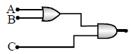
To get an output 1 from the circuit shown in the figure, the input may be :
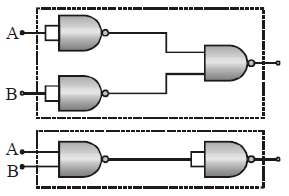
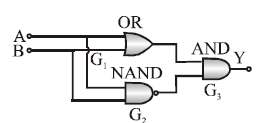
The combination of ‘NAND’ gates shown here under (figure) are equivalent to
In the following circuit the equivalent resistance between A and B is
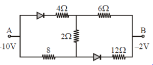
Both the diodes are reversed biased so can be replaced by open circuit.
Req= 8+2+6= 16 ohm
GaAs (with a band gap = 1.5 eV) as an LED can emit :
GaAs (Gallium Arsenide) with a band gap of 1.5 eV can emit light in the infrared region of the electromagnetic spectrum.
The energy of a photon emitted by an LED is related to its wavelength by the equation:
Solving we get
If break down voltage of zener diode is 6 V then value of I2 will be :
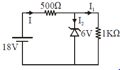
Voltage across 500 ohm resistor = 12 Volt
I = 12/500 = 24 mA
I 1 = 6/1000= 6mA
I2= I - I1= (24-6 )mA= 18 mA
The following configuration of gate is equivalent to
Determine V0 for the network
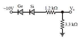
Both the diodes are forward biased so current will flow through the circuit
i= 10/4.5= 20/9 mA
V0= i R= (20/9)×3.3 Volt= 6.6 volt
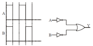
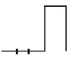
The following figure shows a logic gate circuit with two inputs A and B and the output Y. The
voltage waveforms of A, B, and Y are as given:
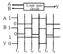
The logic gate is :
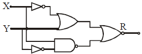
Figure gives a system of logic gates. From the study of truth table it can be found that to produce a high output (1) at R, we must have :
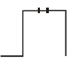
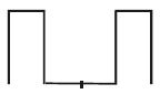
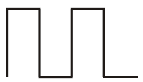
In a given circuit as shown the two input wave form A and B are applied simultaneously. The
resultant waveform Y is :