Question 11:
easy
In series LCR circuit voltage across L, C & R is 20V each. If capacitor is short-circuited then
voltage across inductor is :
In series LCR circuit voltage across L, C & R is 20V each. If capacitor is short-circuited then
voltage across inductor is :
Which of the following plot correctly depicts the variation of phase difference between voltage and current in a series L-C AC circuit ?
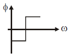
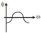
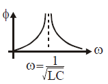
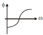
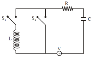
When S1 is closed and S2 is open, \[V_{L}=V_{R}=V_{C}=10V\]. What will be the value of
\[V_{C}\] if S1 opened and S2 is closed ?
A variable inductor is connected to an ac source. What effect does increasing the inductance have on the reactance and current in this circuit ?
A variable capacitor is connected to an ac source. What effect does decreasing the capacitance have on the reactance and current in this circuit ?
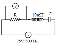
In the circuit of Figure, the volmeter reads 75 V.Value of C is :
Given below are two statements :
Statement I : In an LCR series circuit, current is maximum at resonance.
Statement II : Current in a purely resistive circuit can never be less than that in a series LCR circuit (using same resistance) when connected to same voltage source.
In the light of the above statements, choose the correct from the options given below :
At resonance, impedance of an LCR circuit is minimum and equal to \(R\), so current is maximum. In general, impedance \(Z ge R\), hence the current \(I = V/Z\) is less than or equal to the purely resistive current \(V/R\). Thus, both statements are true.
The maximum power is dissipated for an ac in a/an
The average power dissipated is \(P = V_{\text{rms}} I_{\text{rms}} cos \phi\). For a purely resistive circuit, the phase angle \(\phi = 0\), which gives the maximum power factor \(cos \phi = 1\).
In an LCR series circuit the potential differences across the resistance, capacitance and inductance are \(80\text{ V}\), \(40\text{ V}\) and \(100\text{ V}\) respectively. The power factor of this circuit is:
Total voltage in series LCR is \(V = \sqrt{V_R^2 + (V_L - V_C)^2} = \sqrt{80^2 + (100 - 40)^2} = 100\text{ V}\). Power factor is \(\cos\phi = \frac{V_R}{V} = \frac{80}{100} = 0.8\).
In LCR series circuit the values of \(L\), \(C\), \(R\) and \(E_0\) are \(0.01\text{ H}\), \(10^{-5}\text{ F}\), \(25\ \Omega\) and \(220\text{ V}\) respectively. The value of current flowing in the circuit at \(f = 0\) and \(f = \infty\) will respectively be:
At \(f = 0\), the capacitor acts as an open circuit (\(X_C = \infty\)). At \(f = \infty\), the inductor acts as an open circuit (\(X_L = \infty\)). Therefore, current is zero in both cases.