A parallel plate capacitor has a capacity C. The separation between the plates is doubled and a dielectric medium is introduced between the plates. If the capacity now becomes 2C, the dielectric constant of the medium is :
Let’s solve the problem step by step:
Given:
Initial capacitance:
The separation between the plates is doubled, and a dielectric medium is inserted.
The new capacitance becomes
.
Step 1: Capacitance formula
The capacitance of a parallel plate capacitor is given by:
where:
is the capacitance,
is the permittivity of free space,
is the area of the plates, and
is the separation between the plates.
Step 2: Effect of doubling the separation and adding a dielectric
When the separation
is doubled, the capacitance would normally decrease by a factor of 2 (since capacitance is inversely proportional to
).
Now, when a dielectric of dielectric constant
is inserted, the capacitance increases by a factor of
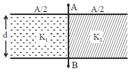
A parallel plate condenser is filled with two dielectrics as shown in figure. Area of each plate is A metre² and the separation is d metre. The dielectric constants are K1 and K2 respectively. Its capacitance in farad will be :
Both the parts can be taken as separate capacitors connected in parallel.
So, C=C1+ C2=\(\frac{\varepsilon_{0A}}{d}\frac{\left( K_{1} +K_{2}\right)}{2}\)
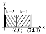
A parallel plate capacitor has two layers of dielectric as shown in figure. This capacitor is connected across a battery. The graph which shows the variation of electric field (E) and distance (x) from left plate.
Given Information:
Parallel plate capacitor: Contains two dielectric layers.
First layer (
) extends from
to
.
Second layer (
) extends from
to
.
Capacitor is connected to a battery: This means the potential difference
across the plates is fixed.
Key Concepts:
Electric Field in a Dielectric:
The electric field
in a dielectric is inversely proportional to the dielectric constant
:
where
is the surface charge density.
Continuity of Potential:
Since the potential
is constant across the capacitor, the sum of the potential drops across the two dielectric layers must equal
. For a uniform electric field in each region:
where
and
are the electric fields in the regions with
and
, respectively.
Relation Between Fields:
The electric displacement
must be continuous across the boundary of the dielectrics:
Substituting
and
, we find:
Explanation of the Graph:
Region 1 (
):
In this region, the dielectric constant
, so the electric field
is relatively stronger compared to the next region.
Region 2 (
):
Here,
, and since
, the electric field is halved.
Thus, the electric field decreases discontinuously at
due to the change in the dielectric constant, leading to the stepwise graph shown in the second figure.
A capacitor stores 60μC charge when connected across a battery. When the gap between the plates is filled with a dielectric , a charge of 120μC flows through the battery. The dielectric constant of the material inserted is :
Given:
Initial charge on the capacitor:
After inserting the dielectric, the total charge from the battery:
(additional charge drawn is
, so the total charge on the capacitor is
).
Key concept:
The charge on a capacitor is given by:
where
is the capacitance and
is the potential difference across the plates.
The dielectric increases the capacitance of the capacitor. If the dielectric constant is
, the capacitance becomes
. Since the battery is still connected, the potential difference
remains constant, and the charge increases proportionally with the increase in capacitance.
Step 1: Relationship between charge and capacitance
Before the dielectric, the charge was
, and after inserting the dielectric, the charge is
.
The ratio of the final charge to the initial charge is proportional to the dielectric constant
:
Step 2: Solve for
Substitute the given values:
Final Answer:
The dielectric constant of the material inserted is 3.
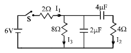
In the circuit shown in the figure, the switch S is initially open and the capacitor is initially uncharged. I1, I2 and I3 represent the current in the resistance 2Ω, 4Ω and 8Ω respectively.
Here's the short solution for the circuit:
Just after the switch is closed:
The capacitors act as open circuits because they are initially uncharged (capacitor voltage cannot change instantaneously).
This means no current flows through the branches containing the capacitors.
Current Distribution:
The total resistance in the circuit is only the sum of the resistors in the main loop (2Ω + 8Ω), as the branches with capacitors are effectively open.
A capacitor of capacitance C is initially charged to a potential difference of V volt. Now it is connected to a battery of 2V Volt with opposite polarity. The ratio of heat generated to the final energy stored in the capacitor will be
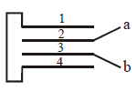
Four metallic plates, each with a surface area of one side A, are placed at a distance d from each other. The plates are connected as shown in the adjoining figure. Then the capacitance of the system between a and b is :
A capacitor is charged by connecting a battery across its plates. It stores energy U. Now the battery is disconnected and another identical capacitor is connected across it, then the energy stored by both capacitors of the system will be
To solve this, we will use the concept of common potential and energy conservation. Let's derive it step-by-step:
Initial Energy Stored in Capacitor 1
Let the initial capacitance of the first capacitor be
, and the battery's voltage be
.
The energy stored in the capacitor is:
When the second capacitor is connected
After disconnecting the battery, an identical capacitor (with capacitance
) is connected across the first one. The total charge remains conserved because the battery is removed. Let the final voltage be
.Total charge initially:
After connecting the second capacitor, the total capacitance becomes:
Common potential
:
Final Energy Stored in Both Capacitors
The final energy stored in the system is the sum of the energy in both capacitors: