Practice NEET Semiconductor Physics Questions
A p–n photodiode is made of a material with a band gap of 2.0 eV. The minimum frequency of the radiation that can be absorbed by the material is nearly :
1. \[1\times 10_{14} Hz\]
2. \[20\times 10_{14} Hz\]
3. \[10\times 10_{14} Hz\]
4. \[5\times 10_{14} Hz\]
View Answer
Energy of EM wave E = hυ
⇒ 2 eV = 6.626 × 10^-34×υ
⇒ \[v= 5\times 10_{14} Hz\]
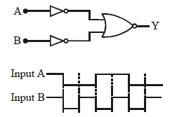
The logic circuit shown below has the input waveforms ‘A’ and ‘B’ as shown. Pick out the correct output waveform.
View Answer
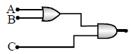
To get an output 1 from the circuit shown in the figure, the input may be :
1. A = 0, B = 1, C = 0
2. A = 1, B = 0, C = 0
3. A = 1, B = 0, C = 1
4. A = 1, B = 1, C = 0
View Answer
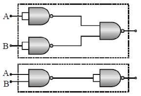
The combination of ‘NAND’ gates shown here under (figure) are equivalent to
1. An OR gate and an AND gate respectively
2. An AND gate and a NOT gate respectively
3. An AND gate and an OR gate respectively
4. An OR gate and a NOT gate respectively
View Answer
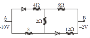
In the following circuit the equivalent resistance between A and B is
1. 20/3 Ω
2. 10 Ω
3. 16 Ω
4. 20 Ω
View Answer
Both the diodes are reversed biased so can be replaced by open circuit.
Req= 8+2+6= 16 ohm
GaAs (with a band gap = 1.5 eV) as an LED can emit :
1. Blue light
2. Green light
3. Infrared rays
4. Ultraviolet rays
View Answer
GaAs (Gallium Arsenide) with a band gap of 1.5 eV can emit light in the infrared region of the electromagnetic spectrum.
The energy of a photon emitted by an LED is related to its wavelength by the equation:
E = h c λ E = \frac{hc}{\lambda}
Solving we get
λ= 826 nm which lies in infrared region.
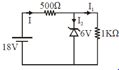
If break down voltage of zener diode is 6 V then value of I2 will be :
1. 18 mA
2. 24 mA
3. 6 mA
4. Zero
View Answer
Voltage across 500 ohm resistor = 12 Volt
I = 12/500 = 24 mA
I 1 = 6/1000= 6mA
I2= I - I1= (24-6 )mA= 18 mA
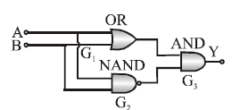
The following configuration of gate is equivalent to
1. NAND
2. XOR
3. OR
4. None of these
View Answer
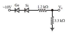
Determine V0 for the network
1. 6.6 V
2. 9 V
3. -9 V
4. -6.6 V
View Answer
Both the diodes are forward biased so current will flow through the circuit
i= 10/4.5= 20/9 mA
V0= i R= (20/9)×3.3 Volt= 6.6 volt
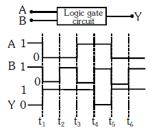
The following figure shows a logic gate circuit with two inputs A and B and the output Y. The voltage waveforms of A, B, and Y are as given:
The logic gate is :
1. OR
2. AND
3. NAND
4. NOR
View Answer