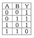
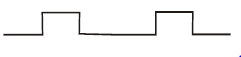
Which of the gates is represented by above?
No solution provided for this question.
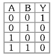
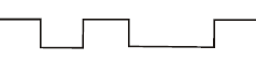
Which of the gates is represented by above?
No solution provided for this question.
In the following circuit, the output Y for all possible inputs A and B is expressed by the truth
table :-
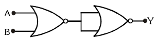
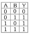
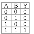
No solution provided for this question.
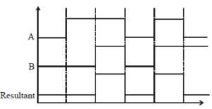
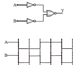
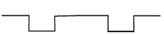
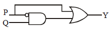
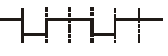
If A and B are input wave forms for given combination of logic gates then output waveform
will be :-
No solution provided for this question.
Find output Y :-
No solution provided for this question.
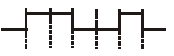
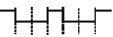
The logic circuit shown below has the input waveforms ‘A’ and ‘B’ as shown. Pick out the
correct output waveform.
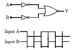
No solution provided for this question.
To get an output 1 from the circuit shown in the figure, the input may be :-
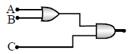
No solution provided for this question.
The combination of ‘NAND’ gates shown here under (figure) are equivalent to
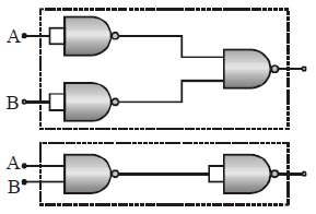
No solution provided for this question.
The following configuration of gate is equivalent to
No solution provided for this question.
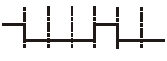
The following figure shows a logic gate circuit with two inputs A and B and the output Y. The
voltage waveforms of A, B, and Y are as given:-
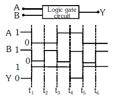
The logic gate is :-
No solution provided for this question.
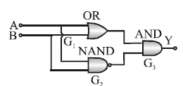
Figure gives a system of logic gates. From the study of truth table it can be found that to produce a high output (1) at R, we must have :
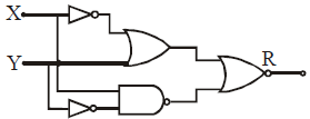
No solution provided for this question.